goodfet
We soldered a special goodfet board, which can not be directly used to do analog-to-digital conversion (pins from the msp430 need to be soldered directly), but can be used a JTAG-tool for the msp430. The soldering guide is found below.
The topic for today is the assembly of the GoodFET, MSP430-programming tool. It is an in-circuit programming tool than can be used for programming, debugging, as a limited oscilloscope and logic analyser. We will use this tool during the course for exactly these reason. Today you will manually assemble the PCB and the components, and put it into operation by using it for analysis.
Disclaimer: this hardware is based on the work of Travis Goodspeed. More information is available at http://goodfet.sourceforge.net/.
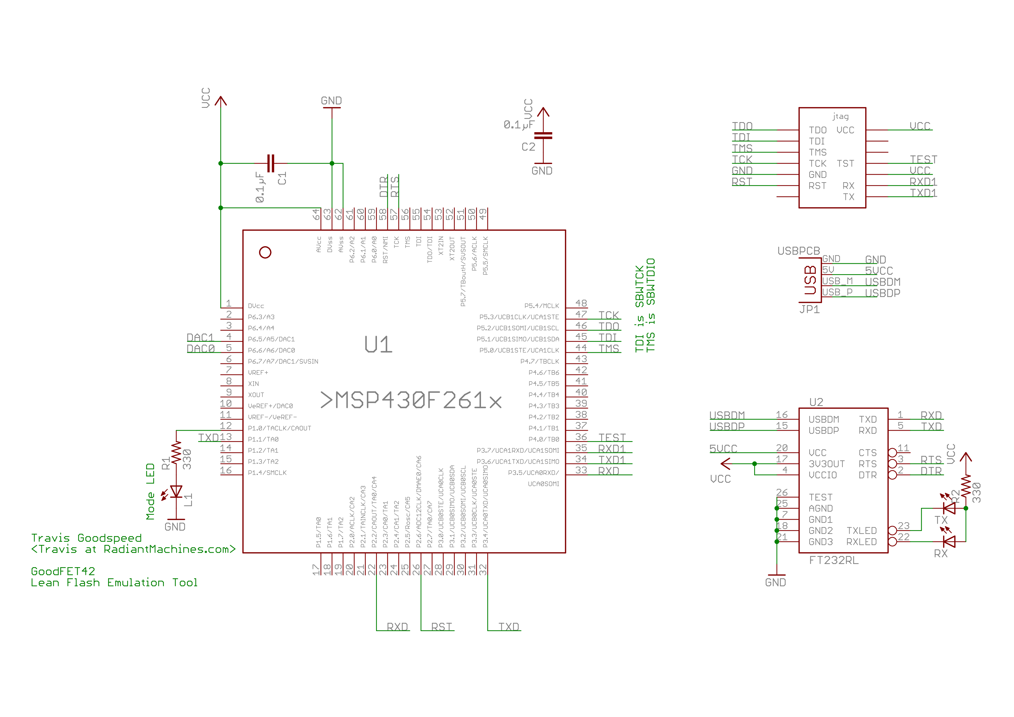
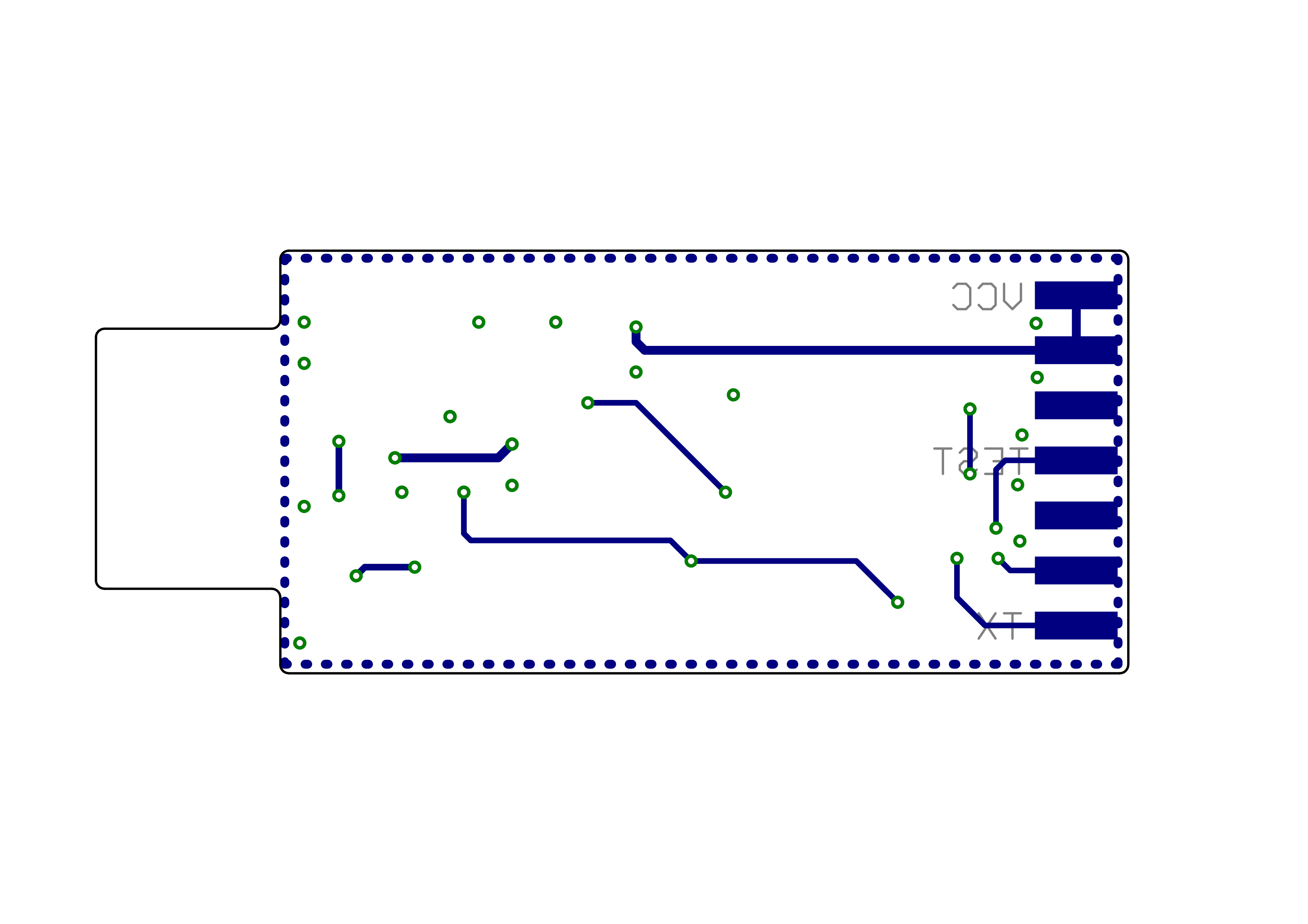
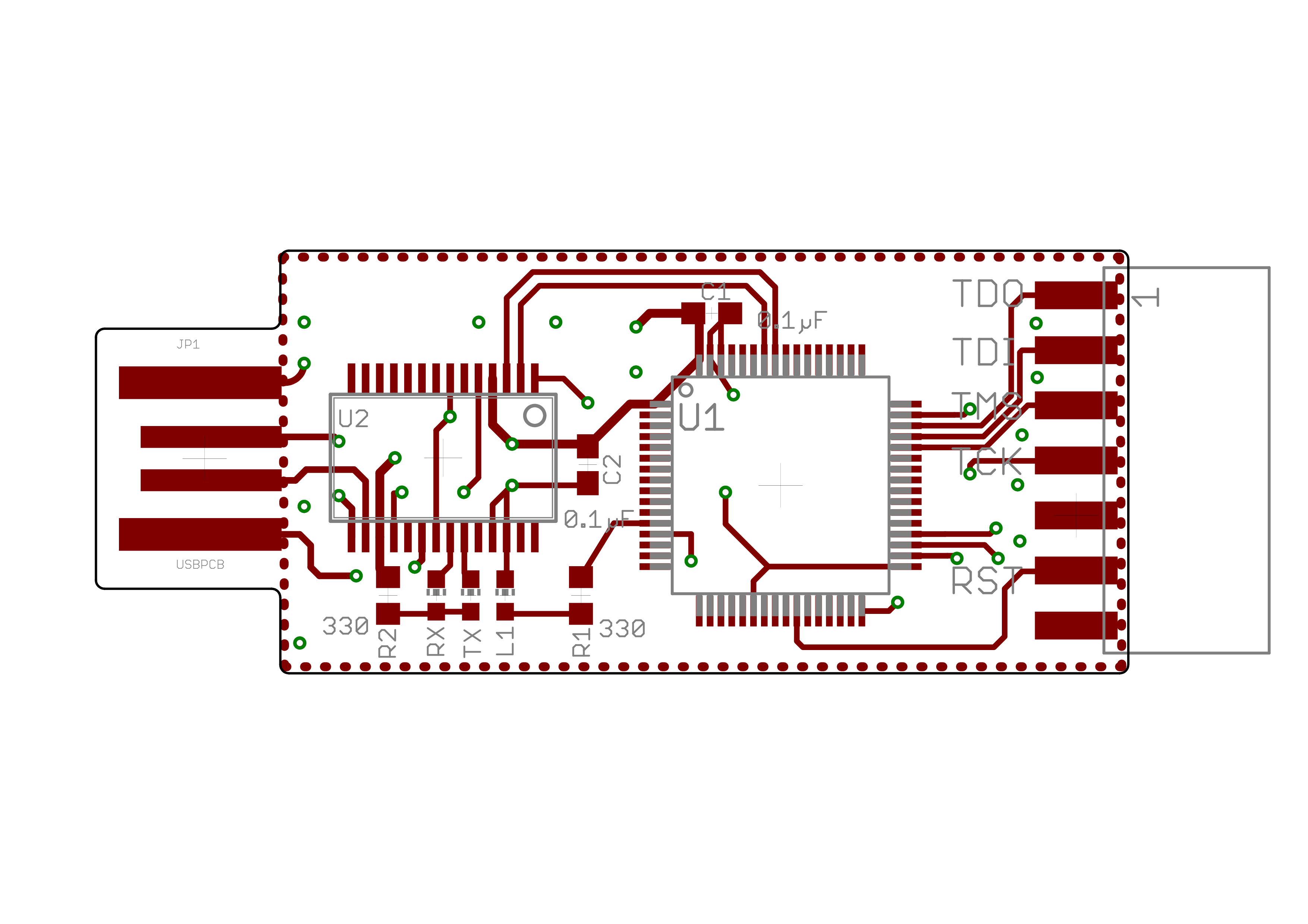
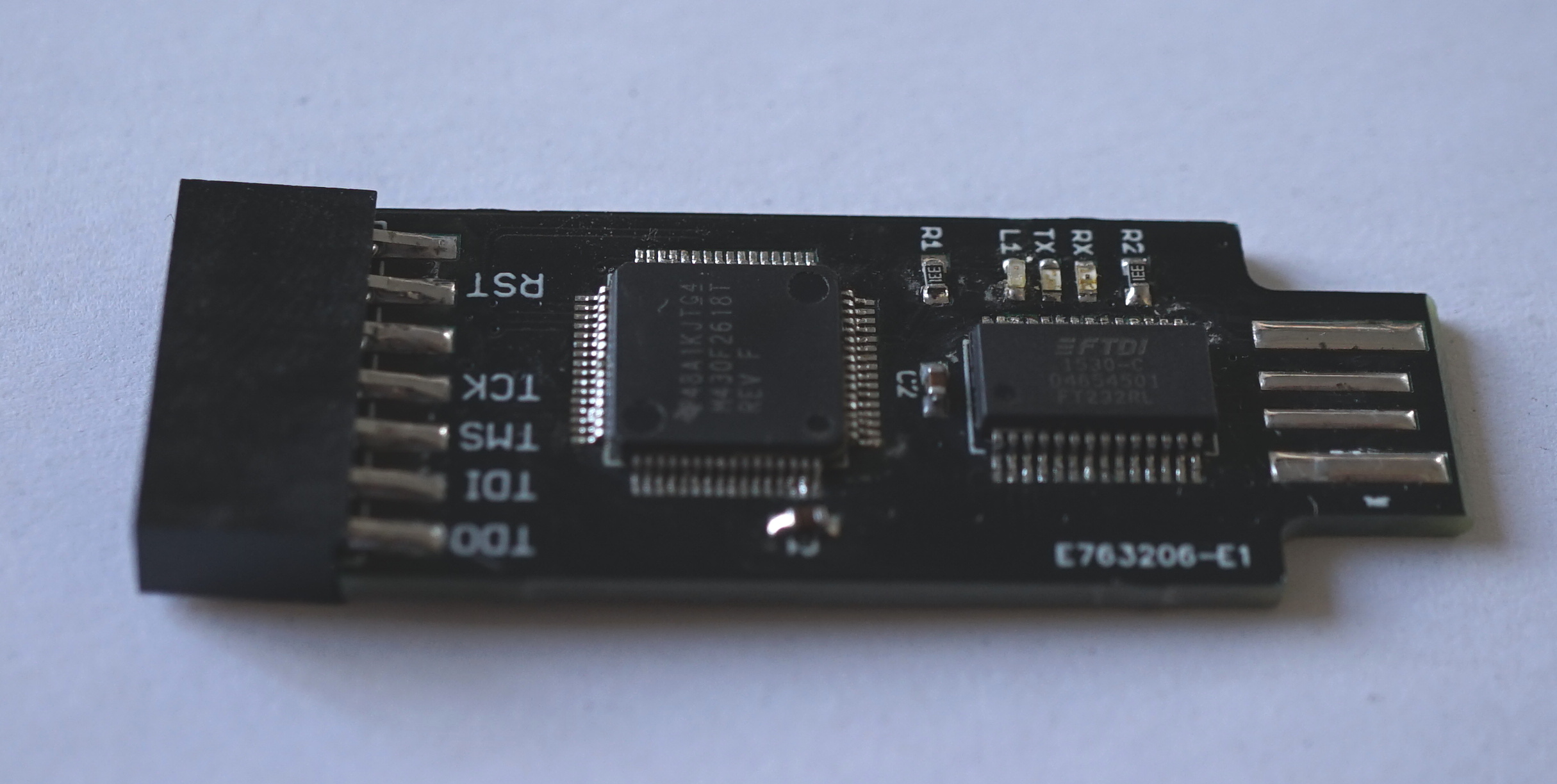
For (almost) every electronic device out there, there is an schematic and printed circuit board (PCB) design. The schematic includes information on which components the device is made of and how these are connected. The PCB design specifies exactly where components are to be placed on a support board, where copper needs to be placed to connect the components and other physical properties. The schematic can of the GoodFET board can be seen in figure \ref{schematic}. Bottom and top layer of the PCB in figure \ref{pcb_bottom} and figure \ref{pcb_top}. All components will be manually soldered.
As the first step gather all the required materials listed in table \ref{bom_tools}. You will want a nice clean desk, and already unpack all the SMD components as trash can built up quickly and will clutter your work area. Make sure your soldering iron and its cable is an easy to reach spot, and avoid cluttering the cable as you might accidentally burn something. If you can grab some extra lighting and turn on your soldering irons. They automatically turn off when resting in their stand. Components are kept in place and moved around with tweezers.
| reference | quantity | material |
|---|
        |   1         |   smd soldering station
        |   1 pair    |   tweezers
        |   some      |   solder
        |   1         |   flux pen
R1 | 1 | 0603 82Ohms resistors R2 | 1 | 0603 330Ohms resistors C1,C2 | 2 | 0603 0.1µF capacitors RX | 1 | 0603 green LED TX | 1 | 0603 amber LED L1 | 1 | 0603 blue LED U1 | 1 | FTDI serial converter chip U2 | 1 | MSP430 µController | 1 | 7x2 socket strip
Keep the tip of your soldering iron clean by pushing it into soldering sponge. Solder will not heat properly on an unclean tip. Soldering works by using the soldering tip to heat up two metal parts. This means you like to put the tip on the metal parts of your components and the pads on your PCB at the same time. Then when both are heated you apply a little solder, which will turn fluid and connect both metal pads. This process usually does not take longer than 1-2 seconds. Too much heat can destroy components. Alternatively, you can apply flux to the PCB pads and the components, then apply a little solder onto the tip of iron. This will burn the flux which is already included in the solder. However if put the solder onto the PCB and components the additional flux will flow the solder to both pads. Again, try not to apply excessive heat to the pads. Also too much pressure destroys the tips, so stay relaxed.
Apply quite a bit of solder to each of the USB pads. Make sure to keep it leveled by moving it with your soldering iron. This is also a first test of your soldering capabilities. Make sure to heat the pad, and apply solder near the soldering tip but not the tip itself. Observe how the solder flow nicely on the heated cooper.
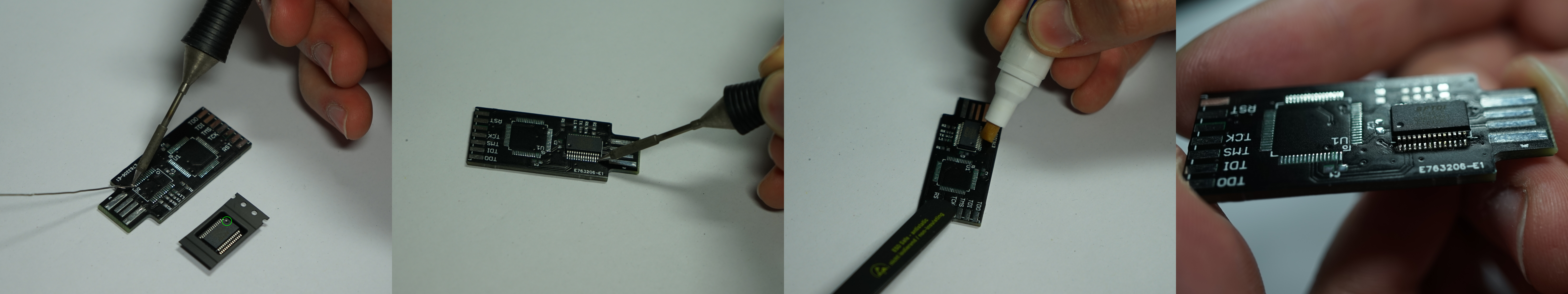
Soldering the ICs looks probably most intimidating, they are however the easiest to solder. Start by finding the pin 1 marking on the IC. This is usually a small dot in one of the corners of the chip. Now find the corresponding marking on the silkscreen of your PCB. For the FTDI this near the USB connector. Fill the pin 1 pad on the PCB with some solder, i.e.~apply some heat with the iron tip and put some solder on. Now grad the IC, heat up the pad again and quickly align it with pin 1 connected. Now apply some flux with the flux pen on all the pads. Now apply some solder to the tip of the iron. Don't wait too long and apply it to one of the unconnected pads. Repeat this step until all pads are connected. Check that all pins are really connected and that there are no short-circuits.
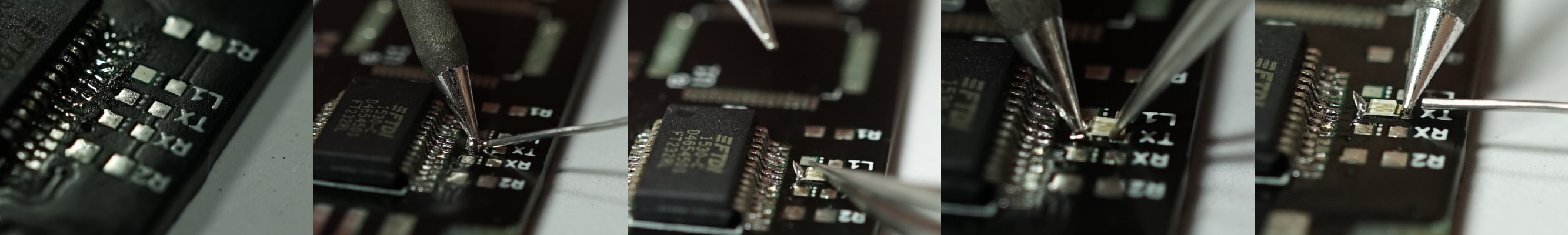
The next step is to solder the caps and resistors. There are not polarized, so you can populate any way you want (even upside-down). Again, apply some solder to one pad first. Then heat it up again, pushing one half of the component in. After the solder has cooled down, you will probably see that there is some space left between PCB and component. In this case put the tweezers on top of the components, heat up the pad again, and apply some pressure to the component, firmly pushing it into place. Then apply solder to the other pad. Again make sure to heat both the pad on the component and the PCB at the same time.
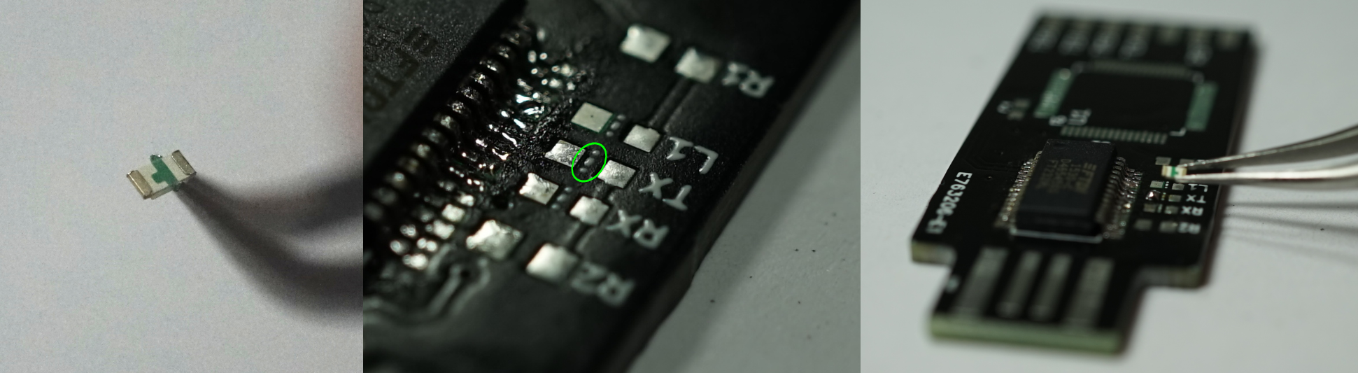
The process for soldering the LEDs is the same as for the caps. With one important difference: LEDs have a polarity. The ground connection of the LED is marked on silk screen with a dotted line. On the bottom of the LEDs you will see a small arrow. The thicker part of this arrow has to match the dotted line. So make sure you watch the orientation of your LEDs while populating them.
This is probably the easiest part. Push the connector into its place, so that the metal pins match the pads. Apply some solder to the heated pins and pads. You might want to put some solder on one of the pads first, so that you do not have to balance the socket strip while heating and holding solder.
Use the provided flux remover (it is actually isopropyl alcohol spray) and some wipe to clean your board of excessive flux.
The GoodFET only runs under Linux, so you might want to use the virtual machine to get the first firmware onto the MSP430 µController. As a first test plug your assembled board into one of your machines. The green led should light up briefly. The serial converter chip should be detected by the Linux system and you can use the ''dmesg'' command to check that. So open up a console and type:
$ dmesg
[376293.116625] usb 1-1.2: new full-speed USB device number 15 using xhci_hcd
[376293.205742] ftdi_sio 1-1.2:1.0: FTDI USB Serial Device converter detected
[376293.205767] usb 1-1.2: Detected FT232RL
[376293.206113] usb 1-1.2: FTDI USB Serial Device converter now attached to ttyUSB0
You should see something similar on your machine. If not either the assembly went wrong somewhere, or the connection on your USB port is not stable enough. In the first case you need to inspect the soldered pads for short-circuits or open connections. In the latter case you can try to apply more solder to the USB pads to increase their height or by using a different (mechanically) USB port. All the installation instruction are also detailed at http://goodfet.sourceforge.net/tutorial/.
We will use ''git'' to download the latest version of the GoodFET software and install it:
$ git clone https://github.com/travisgoodspeed/goodfet goodfet
$ cd goodfet/client
$ sudo make prefix=/usr link
This will install all the executables. A number of prerequisites need be installed, most notable python-sqlite3 and python-serial. You can grab those with these commands:
$ sudo apt-get install python-serial python-sqlite
After that try to execute the ''goodfet.bsl'' executable:
$ sudo goodfet.bsl
Use -h for help
Use --fromweb to upgrade a GoodFET.
Board not specified.  Defaulting to goodfet41.
Press Ctrl+C to cancel, or Enter to continue.
Now we can install the default firmware on the GoodFET:
$ sudo goodfet.bsl --fromweb
Use -h for help
Use --fromweb to upgrade a GoodFET.
Board not specified.  Defaulting to goodfet41.
Press Ctrl+C to cancel, or Enter to continue.
MSP430 Bootstrap Loader Version: 1.39-goodfet-8
Invoking BSL...
Transmit default password ...
Current bootstrap loader version: 2.13 (Device ID: f26f)
Checking for info flash...  None.
Look at contrib/infos/README.txt for better performance.
Grabbing goodfet41 firmware from http://goodfet.sourceforge.net/dist/goodfet41.hex
Mass Erase...
Transmit default password ...
Invoking BSL...
Transmit default password ...
Current bootstrap loader version: 2.13 (Device ID: f26f)
Program ...
25842 bytes programmed.
and run a test to check wether everything works:
$ sudo goodfet.monitor test
See the GoodFET FAQ about missing info flash.
Performing monitor self-test.
Self-test complete.
That's it, you fully assembled and put into operation your first MSP430 programming and debugging tool.