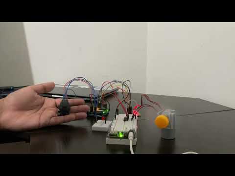
This project uses an Arduino UNO, a joystick module, and an L293DNE motor driver to control a DC motor and a stepper motor. The joystick module allows for manual control of the motors, which can be used in applications such as a fan in this case. Moving the joystick up and down changes the speed of the fan (4 levels including OFF) while moving the fan left and right changes the direction. The OFF mode will be indicated by the red LED. Pressing the switch on the joystick toggles between an automatic (fan oscillates on its own) and manual mode.
All external parts that are used are provided with their appropirate part number (from Digikey).
- Joystick Module (1568-1526-ND)
- L293DNE Motor Driver (296-9518-5-ND)
- DC Motor (1568-1660-ND)
- Stepper Motor (1597-1699-ND)
- ULN2003/X113647 Stepper Motor Driver (1597-1699-ND)
- Breadboard Power Supply Module (377-2647-ND)

Made on Scheme-it (Digikey's Schematic Tool). An external link to the schematic can be found here.

All KiCad files are provided under the "joystick-fan" directory within the repository.
Power supply module should be attached to the breadboard, do not power the motors using the Arduino board.
- VCC -> 5V
- GND -> GND
- VRx -> A0
- VRy -> A1
- SW -> D2
Attach the Stepper Motor Coil to the Stepper Motor Driver. View aforementioned schematic for orientation.
- IN1 -> D11
- IN2 -> D10
- IN3 -> D9
- IN4 -> D8
- GND -> GND
- Connect the DC motor (+) to 1Y (out 1)
- Connect the DC motor (-) to 2Y (out 2)
- 1 (Enable 1) -> D5
- 1A (In 1) -> D4
- GND -> GND
- 2A (In 2) - > D3 PWM
- VCC2 (Motor) -> 5V
- Anode (long leg) -> 220Ω Resistor -> D7 (Power from Arduino)
- Cathode (short leg) -> GND
A physical link is provided here
- Creating a proper 3D printed design for housing the motors and fan
- PCB Design using KiCAD