Multi Attribute Lines
Once upon a time a concealed contact was represented in a GIS as a spatial object accompanied by the single attribute: LTYPE = "contact, concealed". Now, with GeMS, lines have multiple attributes: Type = "contact", IsConcealed="Y", LocationConfidenceMeters=100, ExistenceConfidence="certain", IdentityConfidence="certain". What a pain! Why change?
It is extremely helpful to visualize the multiple attributes of GeMS lines. LocationConfidenceMeters makes more sense once we see it on the map.
How do you efficiently make the multi-attribute lines recommended by the GeMS schema? Here are several possibilities, arranged from most to least desirable:
- Use feature templates that are pre-populated with appropriate clusters of attribute values (Arc 9.3+)
- Populate your database with single-attribute (e.g., LTYPE) lines, and later run a script that translates values of LTYPE into appropriate values of TYPE, IsConcealed, LocationConfidenceMeters, etc.
- Blow it off. Implement single-attribute lines in GeMS
Now you know how to work with multi-attribute lines. What attribute values do you choose?
Values of Symbol can be calculated automatically once values of Type, IsConcealed, ExistenceConfidence, IdentityConfidence, and LocationConfidenceMeters are set. If you change map scale--and thus potentially change which lines are dashed and which are continuous--this calculation is easily repeated.
ContactsAndFaults attributes in GeMS were chosen to provide robust line descriptions, build on the analysis of map lines contained in FGDC Digital Cartographic Standard for Geologic Map Symbolization, and facilitate reuse of map data.
Required line attributes include:
| Attribute | Values | Notes |
|---|---|---|
| Type | contact, fault, waterline, thrust fault, glacier boundary, map boundary, etc. | Values must be defined in Glossary |
| IsConcealed | Y or N | |
| LocationConfidenceMeters | floating point number. Half-width in meters of positional uncertainty envelope | |
| ExistenceConfidence | certain, questionable, unspecified | Values must be defined in Glossary |
| IdentityConfidence | certain, questionable, unspecified | Values must be defined in Glossary |
| DataSourceID | foreign key to DataSources table |
Selection of values for these attributes is discussed in Choosing GeMS ContactsAndFaults attribute values, below.
The three confidence attributes and DataSourceID are feature-level metadata. The draft GeMS standard (pages 9-12) has an extensive discussion of such feature-level metadata.
LocationConfidenceMeters is a floating-point number because it is a real-world quantity, not because we know values to within a gnat's eyelash. Values of LocationConfidenceMeters are recorded as floating-point numbers because they are real, measurable quantities, not because they are precisely known. Even with a factor-of-two uncertainty, author-assigned values of LocationConfidenceMeters are preferable to an unreported value or a value assigned by a third party, perhaps years after the map was made.
Lines also have a ContactsAndFaults_ID attribute, which is a primary key for this feature class. Note that values for all _IDs must be unique within a given geodatabase. Lines also have Symbol, Label, and Notes attributes, though these fields may be empty. If Cartographic Representations are used to symbolize this feature class, RuleID and Override attributes must be present.
Symbol is not the same as Type. The distinction allows easy re-symbolization of a map for different purposes, e.g., editing versus publication.
Some geologic maps characterize contacts and faults as either certain, approximately-located, or inferred. Taken at face value, this three-fold distinction conflates how-located with how-well-located. The distinction obscures the fact that some inferred (not observed) contacts are very well located, whereas other observed contacts are—because of dense brush, poor GPS reception, bad base map, or other factors—not well located at all.
While drafting NCGMP09, the precursor to the GeMS standard, we discussed the possibility of including a HowLocated field in ContactsAndFaults that reported how lines were identified and located: on-the-ground eyeballs, remote sensing, geophysics, petrography, etc. We decided this was a bad idea, as (1) users of our maps are primarily concerned with the content of our maps, not how the maps were made, (2) such information can be conveyed by thoughtful use of the DataSourceID attribute, and (3) the distinction between on-the-ground observation and remote sensing (or geophysics, or ...) is unfortunate. It reflects a lack of appreciation of how obvious and well-located some features are with appropriate remote observation methods and how poorly direct observation allows us to locate and characterize some features.
Paper maps are compromises founded on the limitations of the medium. Only so much information can be packed into a given space on the paper map. We simplify our knowledge so that it can be portrayed on the map sheet and stored in the library.
With the advent of digital databases for storing map information, the space-related compromises of our analog past are no longer necessary. We can make maps that are as rich as we wish them to be. A richer set of line attributes allows us to:
- Communicate better. We unpack the multiple dimensions hidden inside single-attribute lines and explicitly describe each dimension. We move away from esoteric jargon (certain, approximate) and use real-world units (meters) that are widely understood.
- Better re-use data at other scales. Traditional definitions of line accuracy (certain, approximate) are scale-dependent. When we label a line approximate we don't specify how much the scale must shrink before the line becomes certain. With real-world values for LocationConfidenceMeters we confidently and correctly assign symbology (continuous or dashed) at any scale.
- Facilitate queries. Determination of relative map-unit ages and identification of an unconformity do not depend on whether a contact is approximate or certain. All concealed lines should be dropped to build polygons. For a first-cut seismic hazard evaluation it may be appropriate to ask where the nearest fault is. In each of these instances there is a corresponding digital query. With single-attribute lines, these queries often involve complex analysis of text strings and it is easy to code mistakes. Multiple-attribute lines allow simpler query logic that is more likely to be correct.
The transition from paper to digital media does not change the fundamental character of our maps as abstractions of the real world! Storing more information makes our maps richer but does not make them more real. This is OK: geologic maps work because they are abstractions.
While editing a database it is convenient to visualize, at the same time, the multiple attributes of the lines in ContactsAndFaults.
A. Open up ArcMap. Add several instances of the ContactsAndFaults feature class to your data frame.
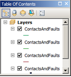
Rename these instances to (approximately) the attributes to be visualized. Note that LocationConfidenceMeters is drawn underneath the other layers.
Highlight all the newly-added layers, right-click, and GROUP the layers. Give the group a useful name, perhaps “ContactsAndFaults.”

B. Double-click on layer LocationConfidenceMeters, or right-click on it and select Properties... This will open the Layer Properties window.

Select the Symbology tab.
Under Show: (left side of LayerProperties window), select Quantities—Proportional symbols.
Set Fields Value: to LocationConfidenceMeters and Normalization to none. Set Unit: to Meters. Under Data represents, select the Distance from Center radio-button.
Set Base Symbol to a simple zero-width line. I suggest choosing white or an intermediate gray as the line color.
Select the Display tab. At the upper left corner of the window, make sure that Scale symbols when a reference scale is set is not checked. Set Transparent: to an intermediate value (perhaps 50%). Click OK.

In image above, note semi-transparent white LocationConfidenceMeters envelopes of several widths.
C. Double-click on layer ExistenceConfidence, or right-click and select “Properties...”
Select the Definition Query tab. Click on “QueryBuilder...” Build a query that selects “ExistenceConfidence”<> 'certain'.

Go to the Symbology tab. Under Show:, select Features—Single symbol. Click on Symbol to bring up the Symbol Selector. Click Edit Symbol.... to bring up the Symbol Property Editor. Under Properties: Type: select Marker Line Symbol. Click on Symbol... and select something simple and open—perhaps a circle. Make it 6 or 8 pts across and red. OK your way out.
D. Repeat with the IdentityConfidence layer, but make the symbol blue. Modify the Template (in Symbol Property Editor) so that markers for the IdentityConfidence layer are not superimposed on markers for the ExistenceConfidence layer.
Note that IdentityConfidence and ExistenceConfidence could also be symbolized without definition queries, using Categories—Unique values (on the Symbology tab).
Symbolization somewhat like this is embodied in the layer file ContactsAndFaults24k.lyr provided in the GeMS_Tools/Resources directory
Specifying values for multiple line attributes is a significant amount of work and slows the process of creating new line features. However, if you are among the many who will be content to use clusters of predefined values for the multiple line attributes of the GeMS schema, the feature templates available in ArcMap since version 9.3 provide a reasonably satisfactory solution to this problem Feature templates (1) provide a point-and-click digitizing menu, and (2) can specify clusters of attribute values.
While the GeMS schema allows for an infinite variety of Type and LocationConfidenceMeters values, we need not use this variety. Eventually we hope there are digitizing interfaces that encourage and ease the use of this variety.
A. Create a proxy (or key) attribute in ContactsAndFaults that will signify the clusters of attribute values. Let's call it LTYPE. You can do this manually in ArcMap or ArcCatalog. It is also an option when using the GeMS Create New Database script.
B. Make a list of commonly-used clusters of values. It should be relatively short—one or two dozen clusters at most. Select names for these clusters that indicate the associated attributes and, when sorted alphabetically, produce a useful ordering. Careful use of spaces helps. See the list below.

C. In ArcMap, add the ContactsAndFaults layer to a mapdocument. Open **Properties...**and set symbolization to Categories—Uniquevalues. Set ValueField to LTYPE. Use Add Values (or Add All Values) to addat least one value of LTYPE to the list of symbols. OK out.
Note that this requires that you have at least one arc in the ContactsAndFaults feature class with a defined value of LTYPE. Add a temporary arc if you need to.
D. Back at the ArcMap Table of Contents, right-click on the ContactsAndFaults layer, select Edit Features, Organize Feature Templates....The Organize Feature Templates window will open.

Click on New Template which will launch the Create New Templates Wizard. Ensure that the ContactsAndFaults layer is selected (and perhaps that other layers are not) and click Next>. You should see a table with one or more templates named with values of LTYPE. Click Finish, then Close.
E. Back at the ArcMap Table of Contents, right-click on the ContactsAndFaults layer, and select Edit Features > Start Editing. You may need to go to the Editor toolbar, click the Editor ▼ dropdown, and select Editing Windows> Create Features. This will bring up the Create Features window which should display the template(s) you created in step 4.
Right-click on a template and select Properties.... Define attribute values for this particular template. I suggest that Name: and LTYPE be identical. Leave ContactsAndFaults_ID empty. Click OK.
Note that Drawing Symbol cannot be changed in the Template Properties window—you have to do this at the Table of Contents or in the Symbology tab of the Layer Properties window.
Create additional templates by right-clicking on a template and selecting Copy. This will immediately create a new template named “Copy of
Here are the templates in ContactsAndFaults24k.lyr:

- Select template names carefully. ArcMap imposes an alphabetical sort. Use spaces and special characters to get the ordering you need. You may decide that values of template name and LTYPE should be different.
- The point-and-click Create Features interface works well with a limited number of choices. Thin your template list to only those needed for a particular digitizing project.
- It is useful to distinguish between editing symbolization and publication symbolization. The symbols we use for publication often aren't sufficiently distinctive for easy editing on a complex backdrop. For a given project I maintain two .mxd files, one for editing and one for the final publication graphic. In the editing .mxd, I symbolize ContactsAndFaults on LTYPE, usually combined with additional ContactsAndFaults layers symbolized on ExistenceConfidence, IdentityConfidence, and LocationConfidenceMeters. In the publication .mxd, I symbolize ContactsAndFaults on Symbol.
- Creating an effective set of templates takes some time. Save time by saving your completed ContactsAndFaults layer—with sublayers, symbolization, and templates—to a .lyr file. See ContactsAndFaults24K.lyr, included with GeMS_Tools. For your next project, load this .lyr file and reset the data sources.
- After a line has been created, changing the value of LTYPE does not change the values of associated attributes. This is unfortunate. If you wish to change the LTYPE (or other key value) of an already-attributed line, you must also change the value of each dependent attribute.
GeMS can be used in ALACARTE single-attribute mode, and with later conversion to multiple line attributes. Necessary steps are
- Create an empty GeMS-style geodatabase using the Create New Database script. Check the box to add LTYPE, PTTYPE, and PTYPE attributes.
- If you already have a database, but without an LTYPE attribute to ContactsAndFaults: Stop Editing, Open the ContactsAndFaults attribute table, and Add Field... LTYPE (Text, length 50) to ContactsAndFaults.
- (Optional) Create a domain of LTYPE values and attach this to ContactsAndFaults field LTYPE.
- Create lines, setting LTYPE values as you go. Or create lines and calculate LTYPE values after the fact, selecting multiple lines and using Field Calculator. Save. Stop Editing.
- Run script Attribute By Key Values (in the GeMS Tools toolbox) to translate LTYPE values into corresponding values of Type, IsConcealed, LocationConfidenceMeters, etc.
- After database is complete, delete LTYPE field,
Steps 2 and 3 may be repeated as needed.
If you are too important to bother with multi-attribute lines, you can implement single-attribute lines in GeMS and produce a quasi-valid database. Stuff “contact, approximate, queried” and similar values into the Type field, with appropriate definitions in the Glossary table. Set LocationConfidenceMeters to -9, ExCon and IdCon to “unspecified”, and use an arbitrary value for IsConcealed. Set all DataSourceIDs to 'DAS1' (= 'This report').
This will be a valid GeMS-style database. The reviewers should object. Your colleagues and your dog will shun you.
Here are some strategies for choosing values of the GeMS line attributes.
Type values are generally easy to choose. Contact, fault, thrust fault, low-angle normal fault, gradational contact, map boundary, neatline, boundary of glacier or permanent snowfield: the universe of likely values is not large. You are free to make up your own values. All values of Type must be defined in the Glossary table within the geodatabase.
Some scripts that operate on ContactsAndFaults parse Type values into 3 classes: contacts, faults, and map boundary. If your fault Types all have 'fault' in them, and the map boundary Type contains 'map' and 'boundary', there should not be a problem.
IsConcealed is either Y or N.
LocationConfidenceMeters can be challenging. We can start with United States National Map Accuracy Standards (http://nationalmap.gov/standards/nmas647.html):
**Horizontal accuracy**. For maps on publication scales larger than 1:20,000, not more than 10 percent of the points tested shall be in error by more than 1/30 inch, measured on the publication scale; for maps on publication scales of 1:20,000 or smaller, 1/50 inch. These limits of accuracy shall apply in all cases to positions of well-defined points only. Well-defined points are those that are easily visible or recoverable on the ground, such as the following: monuments or markers, such as bench marks, property boundary monuments; intersections of roads, railroads, etc.; corners of large buildings or structures (or center points of small buildings); etc. In general what is well defined will be determined by what is plottable on the scale of the map within 1/100 inch. Thus while the intersection of two road or property lines meeting at right angles would come within a sensible interpretation, identification of the intersection of such lines meeting at an acute angle would obviously not be practicable within 1/100 inch. Similarly, features not identifiable upon the ground within close limits are not to be considered as test points within the limits quoted, even though their positions may be scaled closely upon the map.In this class would come timber lines, soil boundaries, etc.
This suggests that for 1:24,000 scale and larger maps, well-defined features (which geologic contacts may not be!) are located within +/- 0.02 inches. At 1:24,000 scale, this is ±12 m on the ground. If lines are originally located on 1:24,000 topographic maps, they cannot be more accurate (have smaller LocationConfidenceMeters values) than this.
A 1956 memo from USGS Chief Geologist W.H. Bradley suggests that accurately located ('certain') features are “located from exposures or other evidence within 1/25 inch [on the map] of their true map position” (quoted in FGDC-STD-013-2006, p. 18). At 1:24,000 scale, this is ±24 m on the ground; at 1:100,000 scale, ±100 m on the ground. There have been significant departures from this suggestion because of the cost of drafting dashed lines, the unreadability of maps with abundant dashed lines, and the recognition that accuracy criteria relevant to the well-exposed desert Southwest are not useful in heavily timbered, drift- or loess-covered terrain elsewhere. The resulting confusion is one of the reasons for using an explicit LocationConfidenceMeters attribute.
What values of LocationConfidenceMeters should you use? If you are translating an existing dataset, appropriate values may be identified in the accompanying metadata. If not, ask the geologist who created the dataset what values are appropriate. Or guess at appropriate values, using Bradley's ±1mm (±1/25 inch) rule, and ask the geologist to confirm them. If the geologist is not available, use your best judgment. In all cases, graphic depiction of LocationConfidenceMeters values will be helpful in evaluating your choices.
Even with a factor-of-two uncertainty, author-assigned values of LocationConfidenceMeters are preferable to an unreported value or a value assigned by a third party, perhaps years after the map was made. -- *[GeMS (Geologic Map Schema)—a standard format for digital publication of geologic maps](https://ngmdb.usgs.gov/Info/standards/GeMS/docs/GeMSv2_draft7g_ProvisionalRelease.pdf), p. 11**
Map boundaries are part of the ContactsAndFaults featureclass, as they participate in the map topology, but they usually do not correspond to locatable real-world features. Set their LocationConfidenceMeters to 0.
ExistenceConfidence and IdentityConfidence are not distinguished on most existing maps. Contacts and faults are simply queried. Your best choice for ascertaining whether a line is queried because ExCon is questionable, IdCon is questionable, or both is to interrogate the geologist responsible for the map. Most geologic maps have few queried lines, thus the amount of work occasioned by interrogating the geologist and individually setting ExCon and IdCon values <> 'certain' will be small.
If there is no responsible geologist to interrogate, use your judgment. You could decide that all queried lines have ExistenceConfidence = questionable, unqueried lines have ExistenceConfidence = certain, and set IdentityConfidence = unspecified for all lines. Please explain what you did in the appropriate entry in DataSources (see below). You could also provide an explanation in the formal metadata for the feature class (or report as a whole).
The DataSourceID field intentionally has great flexibility. At one extreme, a database could have one DataSources entry, e.g., “This report. Contacts, faults, and map units were established in the field, from remote sensing data, and by inference, as well as from previously-published reports and oral and written communications from colleagues. Field work and compilation were done by the authors, assistants, and several colleagues over the last two decades.” Not very informative, but formally correct.
At the other extreme, you could create a separate DataSources entry for every combination of photo pair, field traverse, and bout of compilation and interpretation. This is probably too much detail for most database users!
Where you transcribe an existing map (published or manuscript) and assign LocationConfidenceMeters, ExistenceConfidence, and(or) IdentityConfidence values, this should be noted in the DataSources entry. For example: Doe, J., circa 1960, Geologic map of the Somewhere Quadrangle, unpublished USGS manuscript, scale 1:24,000. Digitally transcribed in 2014 by I.M.A. Geek who, with great trepidation, assigned values of LocationConfidenceMeters, ExistenceConfidence, and IdentityConfidence. If the author was available and helped assign confidence values, say so.
If you truly don't know what the confidence values should be. The GeMS schema suggests that in cases where confidences are truly unknown, ExistenceConfidence and IdentityConfidence may be set to “unspecified”. LocationConfidenceMeters may be set to -9 to indicate an absence of information. If this is a new map—that is, the authors are available but did not help—the reviewers should crucify the authors for this.
Script Set Symbol Values takes a feature dataset, map scale, and threshold values as input and calculates Symbol for some values of Type. Use this script to avoid thumbing through the FGDC symbolization standard; also to re-set symbols when you change map scale.

For the script to work there must be a priori knowledge of Type values, yet in order to provide desirable flexibility the GeMS schema does not prescribe such values. This knowledge is provided in file Type-FgdcSymbol.txt, which is located in the Resources subdirectory of GeMS_Tools. The Type values in this file are taken from the FGDC symbolization standard. If you choose to use a different Type value for, e.g., rotational or scissor fault, reverse-slip offset, edit the appropriate line of Type-FgdcSymbol.txt, inserting your Type value for this concept. You may add additional lines for Type values that are not already present in the file.